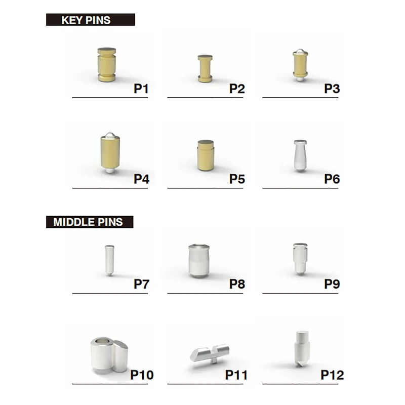
Technical Specifications & Pin Matrix
| Pin Code | Category | Geometric Profile | Material Composition | Primary Engineering Function |
| P1 | Key Pin | Spool / Waist-grooved | Solid Brass | Anti-picking defense (generates false sets) |
| P2 | Key Pin | Dumbbell / Deep-neck spool | Solid Brass | Enhanced anti-picking resistance |
| P3 | Key Pin | Telescopic spool with center core | Brass body + Hardened steel tip | Dual shear-line telescopic anti-pick pin |
| P4 | Key Pin | Telescopic standard with center core | Brass body + Hardened steel tip | Concentric pin-in-pin mechanism pin |
| P5 | Key Pin | Stepped shoulder barrel | Solid Brass | Keyway positioning & bitting tolerance |
| P6 | Key Pin | Tapered / Torpedo profile | Hardened Steel | Anti-bumping & physical drill resistance |
| P7 | Middle Pin | Slender cylindrical with rounded tip | Hardened Steel | Side code / passive profile sensing |
| P8 | Middle Pin | Tapered barrel with retaining rim | Hardened Steel | Lateral blocking & middle tumbler alignment |
| P9 | Middle Pin | Stepped neck with collar | Hardened Steel | Retaining middle pin / pick-resistant driver |
| P10 | Middle Pin | Dual-column / Interlocking body | Hardened Steel / Nickel Alloy | Dual-track side interaction pin |
| P11 | Middle Pin | Horizontal slider with center leg | Hardened Steel | Sidebar locking bar / active floating track element |
| P12 | Middle Pin | Chisel / Wedge-point with top stem | Hardened Steel | Angled key bitting & side gate alignment |
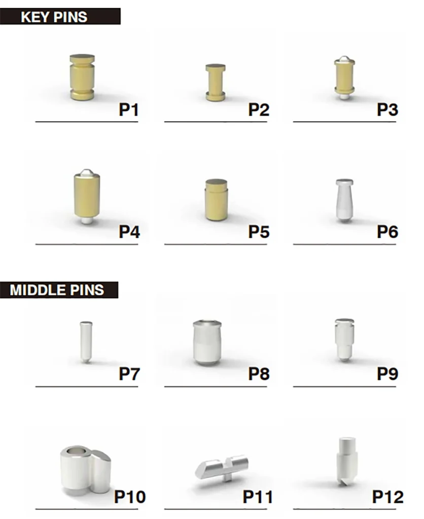
Component Visual Layout & Diagram
Detailed Pin Configuration Breakdown
1. Key Pins (P1 to P6)
Key pins sit directly inside the cylinder plug and make physical contact with the cuts on the key blade:
- P1 & P2 (Spool & Dumbbell Pins): Featuring undercut waists that bind across the shear line if technical picking tools are applied, preventing rotation.
- P3 & P4 (Telescopic Pin-in-Pin Components): Composed of a brass outer sleeve housing an independently moving inner hardened steel pin, designed specifically for dual shear-line telescopic lock mechanisms.
- P5 (Stepped Pin): Incorporates a stepped outer diameter for precise seating in stepped plug chambers.
- P6 (Torpedo Steel Pin): A hardened steel key pin with a tapered contact tip to deflect drilling and resist kinetic bump attacks.
2. Middle Pins (P7 to P12)
Middle pins operate as secondary interactive elements, side pins, or sidebar blockers within complex locking profiles:
- P7 & P8 (Lateral Sensing Pins): Slender and barrel-profile pins designed for side-milled tracks or passive security dimples on the key side.
- P9 (Stepped Middle Pin): Features a specialized collar designed to interact with secondary shear lines.
- P10 (Twin Interlocking Pin): A specialized dual-cylinder geometry providing simultaneous engagement across paired plug chambers.
- P11 (Sidebar Slider / Rocker): A horizontal slider element featuring a central locator leg, designed to interact with active floating elements or side track waves on the key.
- P12 (Chisel-Tip Interactive Pin): Designed with an angled wedge point to engage directional cuts on high-security keys, rotating or lifting to clear the sidebar.
Core Engineering Advantages
Modular Security Customization
Lock manufacturers and locksmiths can mix and match standard pin stacks with these optional components to tailor the cylinder’s defensive capabilities against picking, bumping, or decoding.
Strategic Material Pairing
Pins are fabricated using either high-wear solid brass (for smooth, non-binding daily key insertion) or case-hardened alloy steel (for components subjected to physical drilling or high-stress side blocking).
Multi-Platform Compatibility
Engineered to integrate across European profile cylinders, including standard 7×7 series, telescopic pin-in-pin platforms, and advanced sidebar-assisted cylinders.
B2B Procurement & Supply Terms
- Supply Options: Available as bulk single-code packs (e.g., 1,000 pcs per individual pin code P1–P12) or compartmentalized locksmith pinning replenishment kits.
- Production Lead Time: Typically 25 to 40 days based on batch size and surface finishing requirements.
- Tolerances: Precision-machined under CNC control with dimensional tolerances held within ±0.02 mm.
Frequently Asked Questions
Key Pins (P1–P6) reside in the bottom of the cylinder plug and are directly lifted by the key bitting to reach the shear line. Middle Pins (P7–P12) act as intermediate linkages, side pins, or sidebar gating sliders that interact with secondary key tracks or floating elements.
Yes. All components from P1 to P12 can be ordered as dedicated single-item bulk orders to satisfy specific factory assembly or rekeying requirements.
Yes. The pin diameters and steps are engineered to suit standard European profile plug drillings, ensuring proper spring travel and plug rotation. Contact our engineering team for exact dimensional sheets.